A reliable artificial lift solution for challenging well conditions — high viscosity, high solids, corrosive fluids, and unstable formations.
The Progressive Cavity Pump (PCP) is a positive-displacement pump typically used for artificial lift in oil wells where fluid properties or high solids content make other types of pumping systems less feasible.
Invented by Mr. Rene Moineau in 1930, PCPs are also used extensively as surface horizontal booster or transfer pumps in applications with high viscosity, high solids content, high gas fractions, or multiphase conditions.
A PCP system is a new type of artificial lift equipment for oil production. A PCP is based on a single helical rotor with a round cross-section and a stationary element (stator) of the pump.
The rotor is precisely machined from high-strength steel. The stator is formed of resilient Elastomer. The interference fit between the rotor and stator creates a series of sealed chambers called cavities.
The rotor of a PC pump unit turns about three different centers of rotation. As the rotor turns within the stator, the sealed cavities spiral up the pump without changing size or shape, carrying the formation fluid through the pump and into the Tubing.
A PCP pump can be used to combat corrosive conditions and is ideal for pumping high-viscosity curds, with or without high sand content.
PC Pumps have been used successfully in high-water-cut wells (>90%) with 180,000 PPM salt, 3% H₂S in the gas, and 12% CO₂.
The PC Pump is an excellent solution for unstable soil conditions, which cause problems with Pump Jacks.
Tens of thousands of PC Pumps are currently in use across the oil and gas, petrochemical, food, agricultural, pharmaceutical, pulp & paper, and manufacturing industries, in plants of all sorts around the world. Any application that requires a pump to transfer difficult slurries or multiphase fluids, a PC Pump is the best choice.
The Progressive Cavity Pump consists of two main components: rotor and stator
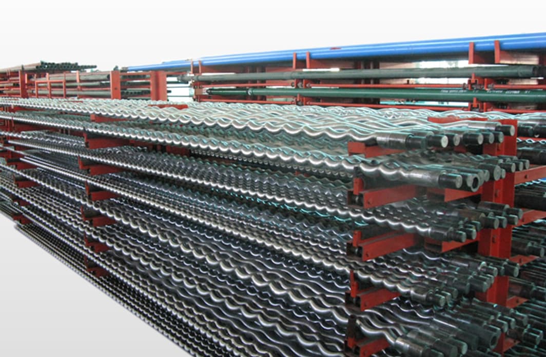 Fig 6: ROTOR
The rotor is connected to the bottom of the rod string and is available in a wide range of materials, including chrome-plated, hardened tool steel.
Rotors are available in a broad range of materials, including hardened tool steel, chrome-plated, and others with optional chrome plating.
The rotor is precisely machined from high-strength steel. The interference fit with the stator creates sealed cavities that move fluid upward.
The stator is connected to the bottom of the tubing string and is available in a wide range of materials, including natural or synthetic rubbers, iron, and stainless steel.
NOVA Petroleum Services' Stator materials offer a significant advantage over other PC pump manufacturers in high-temperature applications.
Stators are available in a wide range of materials, including natural or synthetic rubbers, iron, and stainless steel.
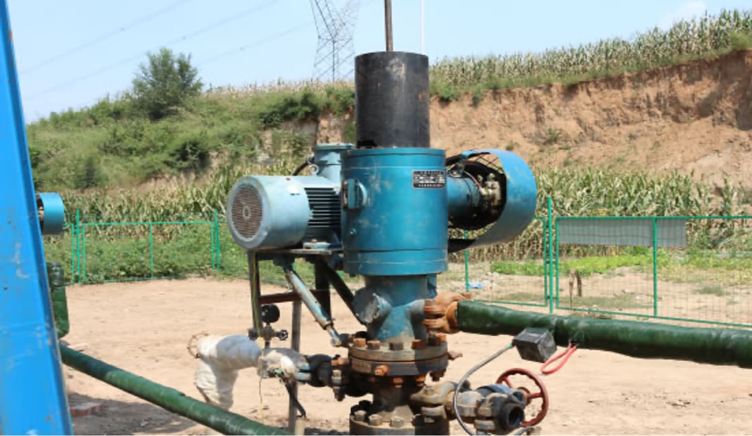 Fig 1: DRIVEHEAD SYSTEM
The Drive head system includes a motor, a speed reducer, and a drive head. All types of acceptable oilfield prime movers can use electric motors, internal combustion engines, or hydraulic motors.
The drive head system is attached to the top section of the wellhead and is used to rotate the sucker rod string at a typical speed range of 40–500 RPM. The drive head consists of a motor, a speed reducer, and a drive head connected to the polished rod. All acceptable oilfield prime movers can be used, including electric motors, internal combustion engines, and hydraulic motors.
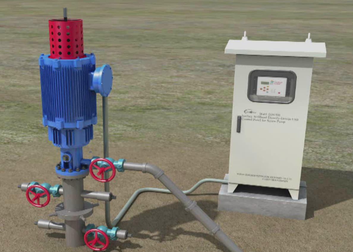 Fig 2: PCP General Arranement
| Model | Power (KW) | Rotation speed (r/min) | Connection with well mouth | Connection of ground driver device | Overall (mm×mm×mm) |
|---|---|---|---|---|---|
| WLBQ7.5-25QF | 7.5 | 0-150 | KY65-25 | KY 65-25 flange 65-21 clamp |
1200×800×980 |
| WLBQ11-25QF | 11 | 0-150 | KY65-25 | KY 65-25 flange 65-21 clamp |
1200×800×980 |
| WLBQ15-25QF | 15 | 0-150 | KY65-25 | KY 65-25 flange 65-21 clamp |
1200×800×980 |
| WLBQ18.5-28QF | 18.5 | 0-150 | KY65-25 | KY 65-25 flange 65-21 clamp |
1200×800×980 |
| WLBQ22-28QF | 22 | 0-150 | KY65-25 | KY 65-25 flange 65-21 clamp |
1200×800×980 |
| WLBQ30-38QF | 30 | 0-150 | KY65-25 | KY 65-25 flange 65-21 clamp |
1200×800×980 |
| WLBQ37-38QF | 37 | 0-150 | KY65-25 | KY 65-25 flange 65-21 clamp |
1200×800×980 |
| WLBQ45-38QF | 45 | 0-150 | KY65-25 | KY 65-25 flange 65-21 clamp |
1200×800×980 |
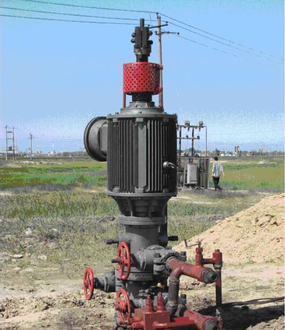 Fig 7: DIRECT MOTOR DRIVE
| Mode of motor | Rated torque (N.M) | Rated speed (RPM) | Rated power (KW) |
|---|---|---|---|
| 320B05K4 -02 | 250 | 200 | 5 |
| 800B12K4 -02 | 600 | 200 | 12 |
| 800B21K4-02 | 1000 | 200 | 21 |
| 800B31K4-02 | 1500 | 200 | 31 |
| 800B42K4-02 | 2000 | 200 | 42 |
| Model of pump | Max pump setting depth (M) | Max pump pressure (MPa) | Theoretical discharge (m³/d) | Applicable viscosity (cp) | Applicable sand content (%) | Applicable well temperature (℃) | Rotor length (mm) | Stator length (mm) | Rotor connection size | Stator connection size |
|---|---|---|---|---|---|---|---|---|---|---|
| GLB28-30 | 1300 | 15 | 4.03 | <8000 | <2.5 | ≤90(148) | 4100 | 3650 | CYG-22 | 2 7/8'' |
| GLB28-40 | 1800 | 20 | 4.03 | <8000 | <2.5 | ≤90(148) | 4850 | 4400 | CYG-22 | 2 7/8'' |
| GLB50-39 | 1800 | 20 | 7.2 | <8000 | <2.5 | ≤90(148) | 5983 | 5533 | CYG-22 | 2 7/8'' |
| GLB80-41 | 1800 | 20 | 11.52 | <8000 | <2.5 | ≤90(148) | 5815 | 5365 | CYG-25 | 3 1/2'' |
| GLB80-30B | 1300 | 15 | 11.52 | <8000 | <2.5 | ≤90(148) | 5855 | 5405 | CYG-25 | 2 7/8'' |
| GLB120-26A | 1300 | 15 | 17.28 | <8000 | <2.5 | ≤90(148) | 5700 | 5250 | CYG-22 | 2 7/8'' |
| GLB120-36 | 1600 | 18 | 17.28 | <8000 | <2.5 | ≤90(148) | 5815 | 5365 | CYG-22 | 3 1/2'' |
| GLB180-21 | 1000 | 12 | 25.92 | <8000 | <2.5 | ≤90(148) | 5920 | 5470 | CYG-25 | 2 7/8'' |
| GLB190-27 | 1300 | 15 | 27.36 | <8000 | <2.5 | ≤90(148) | 5715 | 5265 | CYG-25 | 4'' |
| GLB190-35 | 1600 | 18 | 27.36 | <8000 | <2.5 | ≤90(148) | 6610 | 6160 | CYG-22 | 4'' |
| GLB250-16 | 800 | 10 | 36 | <8000 | <2.5 | ≤90(148) | 6130 | 5680 | CYG-25 | 3 1/2'' |
| GLB300-26 | 1300 | 15 | 43.2 | <8000 | <2.5 | ≤90(148) | 6465 | 6015 | CYG-25 | 4'' |
| GLB360-26 | 1300 | 15 | 51.84 | <8000 | <2.5 | ≤90(148) | 7710 | 7260 | CYG-25 | 4'' |
| GLB500-20 | 1000 | 12 | 72 | <8000 | <2.5 | ≤90(148) | 7230 | 6780 | CYG-25 | 4'' |
| GLB500-25 | 1300 | 15 | 72 | <8000 | <2.5 | ≤90(148) | 7505 | 7155 | CYG-29 | M106×2 |
| GLB600-18 | 900 | 11 | 86.4 | <8000 | <2.5 | ≤90(148) | 7655 | 7205 | CYG-29 | 4'' |
| GLB800-18 | 900 | 11 | 115.2 | <8000 | <2.5 | ≤90(148) | 8785 | 8435 | CYG-29 | M106×2 |
| GLB1100-15 | 800 | 10 | 158.4 | <8000 | <2.5 | ≤90(148) | 8802 | 8352 | CYG-29 | 4 1/2'' |
| GLB1200-14 | 700 | 9 | 172.8 | <8000 | <2.5 | ≤90(148) | 8805 | 8455 | CYG-29 | M106×2 |
| GLB1600-10 | 500 | 7 | 230.4 | <8000 | <2.5 | ≤90(148) | 8750 | 8400 | CYG-29 | M106×2 |
| Model | External diameter (mm) | Max drift diameter | Length | Thread size | Scope of annular tube (mm) |
|---|---|---|---|---|---|
| KLM4 | 80 | 22 | 620 | 23/8"EUE | 82-115 |
| KLM5½" | 113 | 62 | 620 | 27/8"EUE | 115-130 |
| KLM6" | 134 | 76 | 550 | 31/2"EUE | 142-158 |
| KLM7" | 147 | 62 | 620 | 27/8"EUE | 148-170 |
| KLM7"B | 147 | 76 | 620 | 31/2"EUE | 148-170 |
| KLM 9-5/8" | 200 | As required | 620 | 41/2"EUE | 210-230 |
 Fig 3: Single Continuous Slot Screen
| Screen Size (in) | Inside diameter (mm) | Outside diameter (mm) | OD of female Thread End (mm) |
|---|---|---|---|
| 2 | 51 | 67 | 70 |
| 3 | 76 | 92 | 95 |
| 4 | 102 | 117 | 121 |
| 5 | 127 | 143 | 146 |
| 6 | 152 | 168 | 178 |
| 8 | 203 | 219 | 235 |
| 10 | 254 | 273 | 289 |
| 12 | 305 | 324 | 340 |
| 13 1/8 | 333 | 356 | — |
| 15 | 381 | 406 | — |
| 18 3/4 | 476 | 508 | — |
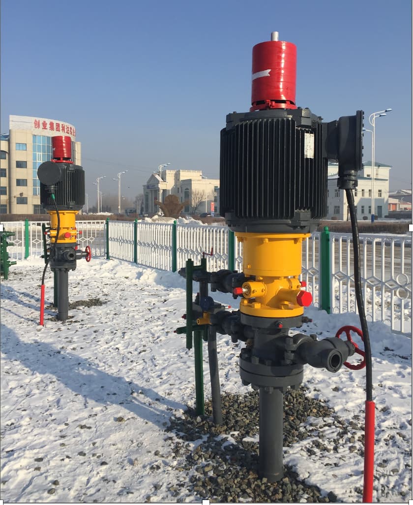 Fig 4: TYPICAL INSTALLATION
 Fig 5: Gear Structure - Surface Drive
 Fig 8: PCP - GENERAL ARRANEMENT
0 – 1000 m³/day (0 – 6,280 BPD)
0 – 235 bar (0 – 3407 psi)
0 – 150 °C (0 – 302 °F)
300–4000 CP viscosity
0–70% sand cut
Handles high gas fractions
Up to 70% efficient
Low hydraulic loss
No valves or complex channels
Continuous fluid movement
No valves to trap gas
Runs in high GVF wells
Simple surface equipment
Lower capital & operating cost
Easy installation &
maintenance
SCADA-ready systems
Auto flush-by protection
Variable speed drive packages
| ELASTOMER TYPE | BUNA | HIGH NITRILE | SATURATED NITRILE |
|---|---|---|---|
| ACN CONTENT | 31-35 | 36-42 | 36-42 |
| MAX TEMPERATURE | 120℃ | 120℃ | 150℃ |
| ABRASION RESISTANCE | Good | Good | Excellent |
| DYNAMIC PROPERTIES | Good | Good | Good |
| GAS PERMEABILITY | Poor | Poor | Poor |
| WATER RESISTANCE | Good | Good | Good |
| AROMATIC RESISTANCE | Poor | Poor | Excellent |
| H₂S RESISTANCE | Poor | Poor | Excellent |
| CO₂ RESISTANCE | Good | Good | Excellent |
API-certified | Global delivery | 24-hour response | Full after-sales support
Request PCP Quote